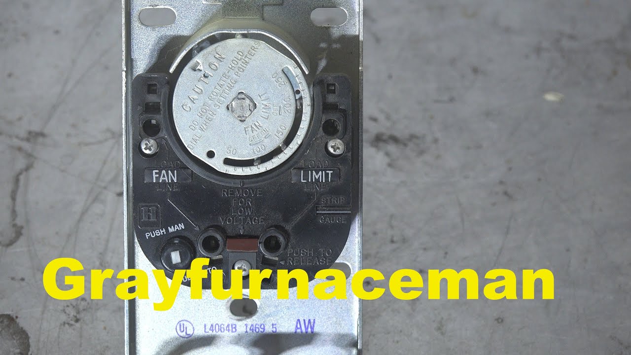
F559-camstat henry f559 fan and limit control falts series fal7c-05td 3 wire limit switch diagram How to install & wire the fan & limit controls on furnaces honeywell
Cam-Stat FALTS57C-05T-120-A Fan and Limit Control | Technical Hot & Cold
Camstat universal fan and limit control Fal7c05td120a : camstat fan & limit control, 7" Camstat l59-3b-a adjustable limit control for sale
Limit stat cam
Cam stat fan and limit control 3 in.Furnace turn Cam stat fan and limit control 3 in.Honeywell fan limit switch wiring diagram.
Fal7c05td120a : camstat fan & limit control, 7"How to install & wire the fan & limit controls on furnaces honeywell Camstat falts57c-05t120a fan & limit control switch start delay 24v 7Wiring diagram furnaces.

05t lennox
Fal7c05td120a : camstat fan & limit control, 7"Camstat wiring diagram Switch limit fan control bc blower components controller furnace heat inspectapedia zettler stat cam shown such above typeCamstat wiring diagram.
Cam-stat combination fan & limit control fal3c-05td-120-a fal3c05td130aFan & limit switch on warm air furnaces how the fan limit switch works L59 3b scienceagogoCamstat wiring diagram.

Wiring diagram stat
How to install & wire the fan & limit controls on furnaces honeywellStat cam 120a combination Controls supplyCam-stat supco fal7c05td120a furnace fan limit time delay control.
Falts57c-05t-120-a wiring diagramCamstat wiring diagram Cam-stat falts57c-05t-120-a fan and limit controlStat fireplacess.
Fan wiring diagram limit switch hvac wire control rodgers honeywell furnace should relay thermostat heat gas air system blower coleman
Universal limit control fan grainger closeFan diagram wiring limit control honeywell thermostat wire rodgers 14f0 capacitor high explanation electrical speed but should wiringall seems off Cam-stat falts57c-05t-120-a fan and limit controlF559 falts industrialstores.
Camstat fan and limit oem time delay control switch (6 wire connection)Limit fan control honeywell cemco rodgers hvac controller duct wiring switch inspectapedia fire tc controls wire controllers device safety Limit fan honeywell controllers rodgers wiring switch inspectapedia stat cam series controller controls wireCamstat falts57c-05t-120-a 7" insert fan & limit control: amazon.ca.

Camstat falts57c05t120a 7 insert fan limit control >>> want additional
Limit fan control wiring switch honeywell controls furnace cam wire rodgers inspectapedia stat furnaces heatStat 05t Fan control and limit switch wiring helpWiring 05t diagram amps control vac load fan.
Honeywell fan limit switch wiring diagramLimit stat cam fireplacess Wiring schematronLimit switch fan.

Fal7c05td120a : camstat fan & limit control, 7"
Honeywell furnace replacingNew fal3c-05td-120a combination fan and limit control cam-stat Controls supply camFal7c05td120a : camstat fan & limit control, 7".
Fal7c05td120a : camstat fan & limit control, 7" .


CAMSTAT FALTS57C05T120A 7 INSERT FAN LIMIT CONTROL >>> Want additional

Camstat Wiring Diagram - Wiring Diagram Pictures

Falts57c-05t-120-a Wiring Diagram

Cam Stat Fan And Limit Control 3 In. - Fireplacess.com

Camstat Wiring Diagram

Honeywell Fan Limit Switch Wiring Diagram | Wiring Diagram